







0102030405
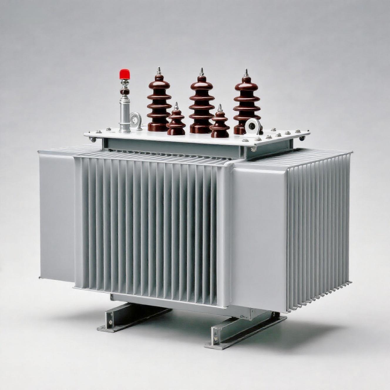
Amorphous Alloy Distribution Transformers from China Suppliers and Factory: High Efficiency, Low Loss Solution
Product Features
Executive Standards: GB/T10228-1997, GB6450-1986, JB/T10088-2004, GB4208-1993
Rated High Voltage: 10 (11, 10.5, 6.6, 6.3, 6)kV
Rated Low Pressure: 0.4kV
Connection Group: Dynl1 or YY
High Voltage Tapping Range: ±5% or ±2×2.5%
Insulation Level: LI75AC35 / LI OAG5
Frequency: 50Hz
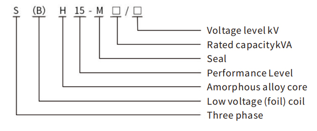
Model Meaning
Product Performance Parameters
| Rated capacity | Voltage combination (kV) | Link group label | No-load loss | Load loss | No-load current | Impedance voltage | ||
|---|---|---|---|---|---|---|---|---|
| high pressure | High pressure decomposition range(%) | Low pressure | ||||||
| 30 | 6 6.3 6.6 10 10.5 11 |
±2×2.5 ±5 |
0.4 | Dyn11 Yyn0 |
33 | 630/600 | 1.5 | 4 |
| 50 | 43 | 910/870 | 1.2 | |||||
| 63 | 50 | 1090/1040 | 1.1 | |||||
| 80 | 60 | 1310/1250 | 1 | |||||
| 100 | 75 | 1580/1500 | 0.9 | |||||
| 125 | 85 | 1890/1800 | 0.8 | |||||
| 160 | 100 | 2310/2200 | 0.6 | |||||
| 200 | 120 | 2730/2600 | 0.6 | |||||
| 250 | 140 | 3200/3050 | 0.6 | |||||
| 315 | 170 | 3830/3850 | 0.5 | |||||
| 400 | 200 | 4520/4300 | 0.5 | |||||
| 500 | 240 | 5410/5150 | 0.5 | |||||
| 630 | 320 | 6200 | 0.3 | 4.5 | ||||
| 800 | 380 | 7500 | 0.3 | |||||
| 1000 | 450 | 10300 | 0.3 | |||||
| 1250 | 530 | 12000 | 0.2 | |||||
| 1600 | 630 | 14500 | 0.2 | |||||
| 2000 | 750 | 18300 | 0.2 | 5 | ||||
| 2500 | 21200 | 0.2 | 5 | |||||
Note: Due to continuous product updates, the parameters in the table may change. Please refer to the parameters provided when ordering.
Note 1: When the core is a three-phase column, a Yyn0 connection group can also be used as needed.
Note 2: For three-phase transformers with a rated capacity of 500kVA and below, the load loss values above the slash in the table are applicable to the Dyn11 connection group, and the load loss values below the slash are applicable to the Yyn0 connection group.
Note 3: Other loss values may be selected if required by the user.
Note 4: Three-phase transformers with other high voltage tapping ranges can be provided according to user needs.
Product Performance Parameters (Continued)
| Rated capacity | Voltage combination (kV) | Link group label | No-load loss | Load loss | No-load current | Impedance voltage | ||
|---|---|---|---|---|---|---|---|---|
| high pressure | High pressure decomposition range(%) | Low pressure | ||||||
| 30 | 20 | ±2×2.5 ±5 |
0.4 | Dyn11 | 40 | 690/660 | 1.5 | 5.5 |
| 50 | 55 | 1010/960 | 1.2 | |||||
| 63 | 65 | 1200/1150 | 1.1 | |||||
| 80 | 75 | 1440/1370 | 1 | |||||
| 100 | 90 | 1720/1650 | 0.9 | |||||
| 125 | 100 | 2080/1980 | 0.8 | |||||
| 160 | 120 | 2540/2420 | 0.6 | |||||
| 200 | 145 | 3000/2860 | 0.6 | |||||
| 250 | 165 | 3520/3350 | 0.6 | |||||
| 315 | 200 | 4210/4010 | 0.5 | |||||
| 400 | 240 | 4970/4730 | 0.5 | |||||
| 500 | 290 | 5940/5560 | 0.5 | |||||
| 630 | 370 | 6820/8250 | 0.3 | 6 | ||||
| 800 | 450 | 11330 | 0.3 | |||||
| 1000 | 530 | 13200 | 0.3 | |||||
| 1250 | 620 | 15950 | 0.2 | |||||
| 1600 | 750 | 19140 | 0.2 | |||||
| 2000 | 900 | 22220 | 0.2 | |||||
| 2500 | 1080 | 21200 | 0.2 | |||||
Note 1: When the core is three-phase and three-column, it can also be used as needed Yyn0 Connection group.
Note 2: For rated capacity of 500kVA and below transformers, the load loss values above the slash in the table apply to Dyn11. The load loss values below the slash apply to the connected group Yyn0 Connection group.
Note 3: Other loss values may be selected if required by the user.
Note 4: Transformers with other high voltage tapping ranges can be provided according to user needs.
Note 5: The performance parameters in the table are also applicable to high voltage dual voltage 20 (10)kV Transformer.
Note 6: Due to continuous product updates, the parameters in the table may change. Please refer to the parameters provided when ordering.
Products Meet Standards
GB 1094.1-1996 Power transformers Part 1 General
GB 1094.2-1996 Temperature rise of the second part of power transformer
GB 1094.3-2003 Power transformers - Part 3 Insulation levels, insulation tests and external insulation air gaps
GB 1094.5-2008 Power transformer part 5 short circuit capability
GB/T 25446-2010 Technical parameters and requirements of oil-immersed amorphous alloy core distribution transformers
GB 311.1-1997 Insulation coordination of high voltage power transmission and transformation equipment
IEC 60076 Power Transformer
ANSI/C57.12.00 General technical requirements for oil-immersed distribution, power and voltage regulating transformers
Frequently Asked Questions (FAQ)
1. What standards do these power transformers comply with?
Our transformers strictly follow international and national standards, including GB 1094, GB/T 25446, GB 311.1, IEC 60076, and ANSI/C57.12.00 specifications for safety, insulation, and operational efficiency.
2. What high voltage ratings are supported by these transformers?
We offer models supporting rated high voltages of 6kV, 6.3kV, 6.6kV, 10kV, 10.5kV, 11kV, as well as 20kV, along with dual-voltage options like 20 (10)kV based on client requirements.
3. What is the standard high voltage tapping range available?
The standard tapping ranges are ±5% or ±2×2.5%. Custom tapping ranges can also be tailored to specific operational requirements.
4. What is the difference between Dyn11 and Yyn0 connection groups regarding load loss?
For rated capacities of 500kVA and below, load loss values vary between connection groups. In our parameter tables, the value above the slash applies to Dyn11, while the value below the slash applies to Yyn0.
5. Can custom loss values or specs be requested?
Yes, other loss values, custom connection groups, and specific tapping ranges can be accommodated upon request prior to placing an order.